In the architecture, engineering, and construction (AEC) industry, the terms BIM, CAD, and VDC are often used interchangeably. While all three involve digital models and contribute to project delivery, they work at distinct levels, from basic design representation to integrated project management strategies.
Knowing these differences is vital for professionals wanting to optimize project outcomes and meet modern regulatory standards, such as Singapore’s CORENET X digital submission guidelines. Understanding where each methodology sits in the project lifecycle also helps teams apply the right tools at the right stage and remain compliant with the requirements that Singapore’s built environment now demands.
3D CAD: The Foundation of Digital Design and Documentation
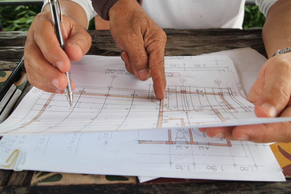
Computer-Aided Design (CAD) is the first and most established digital design technology. It replaced traditional paper-and-pencil drafting. CAD allows professionals to create precise digital representations of physical objects through 2D drawings and 3D models. For decades, it has been the backbone of design workflows, especially in manufacturing industries, like consumer electronics and complex machinery, where accuracy is critical.
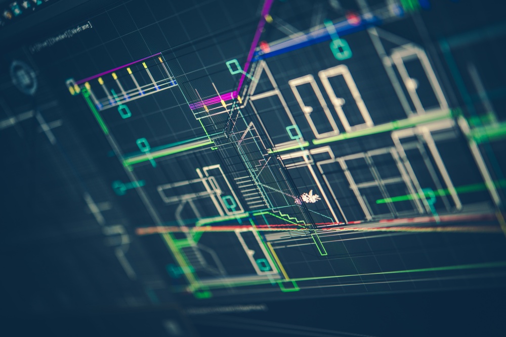
In construction, 3D CAD serves as a design and documentation tool. It excels at representing geometry, dimensions, and spatial relationships, making it ideal for drafting floor plans, elevations, and technical schematics. However, its capabilities are limited to visual and geometric data.
Unlike BIM, CAD does not contain embedded information about materials, performance, or lifecycle attributes. This limitation is one of the key differences between 3D CAD and BIM. CAD shows what something looks like, but it does not show what it really is.
In Singapore, CAD has transitioned from the main submission format to a supporting tool, used for detailed technical drawings rather than integrated digital submissions. CORENET X requires regulatory submissions in IFC+SG-formatted 3D models, a standard that 2D CAD was never designed to meet.
Building Information Modeling (BIM): The Data-Rich Collaborative Workflow
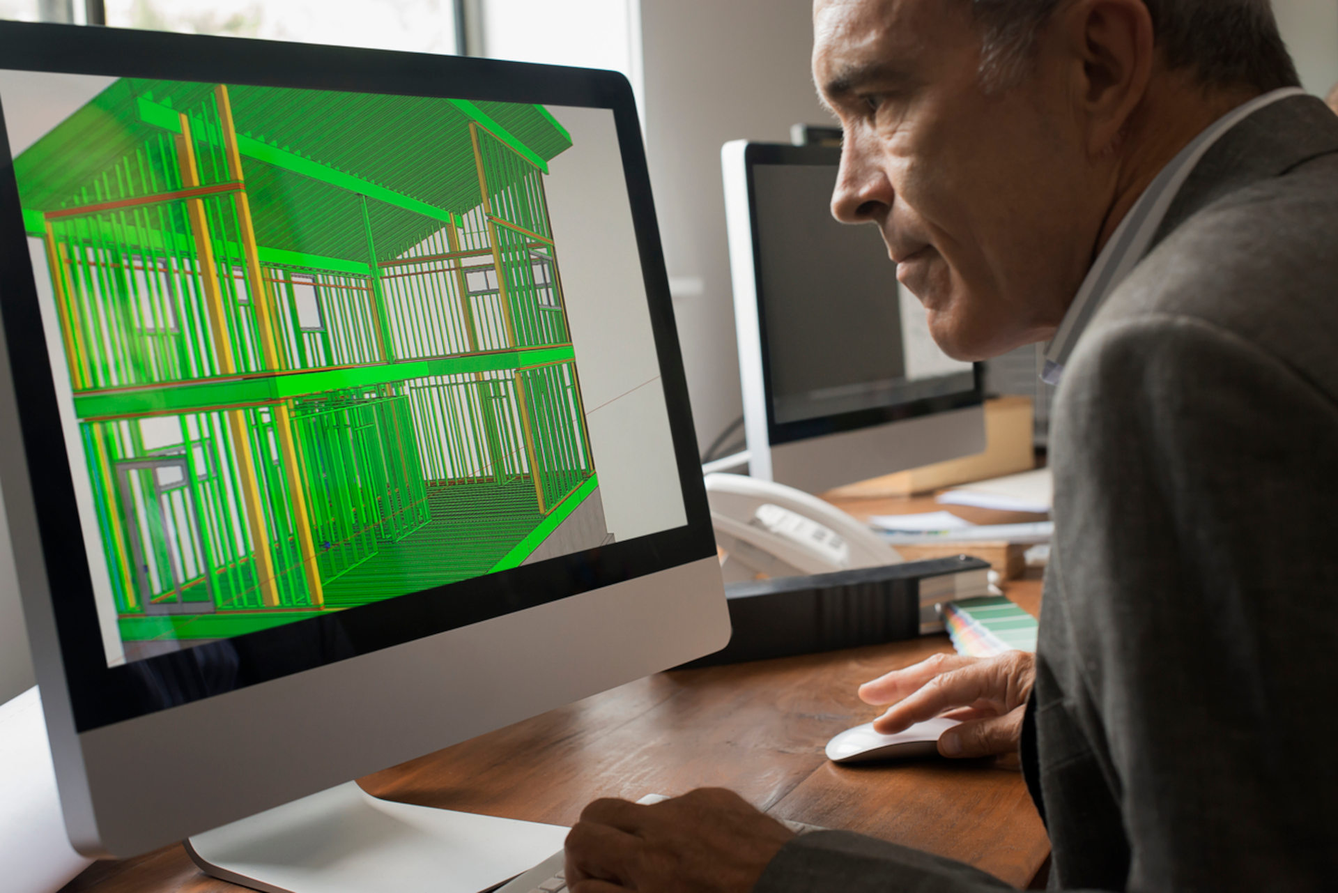
Building Information Modeling is a significant step up from traditional CAD. Instead of just being a tool, BIM is a process that enables professionals to collaborate using intelligent digital models. These models do more than represent shapes; they also include important embedded data, such as materials, fire safety ratings, structural properties, and cost information.
BIM lets every stakeholder involved (architects, engineers, contractors, and clients) work together from the same set of information. This keeps the work consistent, reduces errors, and makes multidisciplinary coordination far more manageable.
Key functional benefits of BIM include:
Clash Detection: BIM helps teams identify conflicts between different building systems before construction begins. Structural versus MEP clashes, for example, can be resolved in the model rather than on-site, where corrections are far more costly.
Parametric Intelligence: BIM objects are “smart.” If something changes, like wall thickness or material, those updates automatically propagate across all linked drawings and schedules.
Lifecycle Utility: Unlike CAD, BIM models remain useful after construction. They serve as a digital reference for facility management, planning repairs, and future alterations.
When comparing 3D CAD and BIM, it is useful to view CAD as a digital drafting tool and BIM as the data-driven workflow that improves collaboration and decision-making throughout the project lifecycle.
For teams looking to operate at this level, structured BIM training is necessary to ensure that staff can handle the data requirements of modern regulatory compliance, including CORENET X submissions in IFC+SG format.
Virtual Design & Construction (VDC): The Integrated Management Strategy
Virtual Design & Construction (VDC) is the most sophisticated of the three methodologies. While BIM focuses on creating intelligent models, VDC operates at a higher level, coordinating people, processes, and technology across the entire project lifecycle, with BIM-generated data as its primary input.
BIM is a Component of VDC: BIM provides the data-rich models that VDC relies on.
VDC Extends Beyond BIM: It includes scheduling (4D), cost estimation (5D), resource planning, and performance metrics.
VDC is Strategy-Driven: It focuses on how teams work together, make decisions, and complete projects efficiently, not just on building models.
In simpler terms, regarding the VDC BIM meaning, if BIM answers “what does the building contain?”, VDC answers “how do we deliver this project optimally?”
In practice, tools like Fuzor VDC are often used within VDC workflows to enhance visualization, simulation, and construction sequencing. Given its complexity, successful implementation often requires structured VDC training to align teams on processes, coordination strategies, and performance measurement.
Industry Scopes: Determining Which Methodology Fits Your Project
Each method has its own role in the AEC industry, and knowing where they fit is key to choosing the right approach.
3D CAD: Best suited for industries that need highly precise design and engineering, such as manufacturing and product development. In construction, it is still useful for making detailed drawings and technical documents.
BIM: BIM is now the standard for commercial building projects, like schools, offices, hospitals, and transport systems. BIM helps coordination across disciplines, supports regulatory compliance, and integrates seamlessly with cloud platforms often delivered via an Autodesk Cloud Solution reseller.
VDC: Designed for large, complex projects that require careful planning and multidisciplinary coordination. It brings together digital tools (like CAD and BIM) with project management methods to help people communicate, reduce risks, and make the project run smoothly.
These methods do not compete with each other; they work together. CAD provides basic shapes, BIM adds collaboration and data, and VDC brings it all together with a single plan for managing the project.
By partnering with experts who truly understand the meaning of BIM and VDC, and its impact on the project lifecycle, your firm can ensure every build is efficient, compliant, and future-ready. Navigate the complexities of modern construction with BIMAGE Consulting today.
Across Singapore’s built environment, Building Information Modeling (BIM) and Revit are still used interchangeably by many practitioners.
They shouldn’t be.
While both contribute to coordinated, data-rich 3D building design, they operate at fundamentally different levels. One is a methodology that governs how information is created, managed, and shared across an entire project lifecycle. The other is software used to implement that methodology.
The distinction has always mattered, but the stakes are higher with the implementation of CORENET X. Singapore’s integrated regulatory submission platform now requires BIM-formatted 3D models in IFC+SG format. A team that treats BIM only as software will likely configure Revit for visualisation. Conversely, a team that treats BIM as a process will configure Revit to produce regulatory-grade, data-enriched models that pass the CORENET X Automated Model Checker. Only the latter approach ensures compliance.
Breaking Down the Terminology
Both terms are conflated in part because Revit is so dominant in Singapore’s AEC sector that the workflow and methodology can feel inseparable. But as mentioned, they aren’t.
The Big Picture: What is Building Information Modeling?
BIM is a process and a methodology for managing building information across an asset’s entire lifecycle. In Automation in Construction, it is defined as a data-driven methodology that bridges the gap between technology and policy. It provides a standardized digital environment to oversee a project’s critical information, transforming how building data is managed and utilized throughout its entire life cycle.
The process is not defined by a single file or programme. It spans design, construction, and facilities management, underpinned by a shared knowledge resource that all project stakeholders can access and contribute to throughout the asset’s life.
International Standards: ISO 19650 provides the global framework for information management, ensuring the right data is delivered in the right form at the right stage.
Singapore Standards: The BCA aligns with these principles through the BIM Essential Guide and CORENET X requirements, which demand that information be structured and coordinated to support automated regulatory review.
The Digital Engine: What is Autodesk Revit?
Autodesk Revit, on the other hand, is a software application built specifically to support the BIM process. It covers the three core disciplines of the AEC industry: architectural design, MEP (Mechanical, Electrical, and Plumbing) engineering, and structural engineering.
Unlike 2D CAD, which represents a wall as a simple line, Revit treats it as a parametric object. This object carries embedded metadata, including:
Material composition and thickness
Fire rating and acoustic properties
Cost parameters and more
This structured data is what makes a Revit model genuinely “BIM-capable” rather than just a visual 3D representation.
What is the Difference Between BIM and Revit? Distinctions Between the Methodology and the Tool
Think of BIM as the game plan and Revit as one tool for executing it. In practical terms, the key differences are:
AutoCAD’s role in this picture has narrowed considerably. Because 2D drawings cannot carry the structured, object-based metadata required for automated model checking, AutoCAD is insufficient for CORENET X submissions. As regulatory agencies transition to IFC-SG 3D models, 2D drafting is no longer a viable substitute for compliant project delivery.
The Synergistic Relationship Between the Process and the Platform
Understanding the distinction is one thing. Seeing how BIM and Revit work together in practice is where that understanding becomes productive. Configured correctly, Revit is not just BIM-compatible software; it becomes the primary environment in which BIM principles are translated into tangible project deliverables.
Implementing the BIM Framework via Revit
Revit utilises parametric objects as virtual equivalents of real building components. This database-driven approach ensures that a change made to a wall section is automatically propagated across all schedules, plans, and elevations. This eliminates the version-control errors inherent in 2D workflows and maintains model coherence across complex, multidisciplinary changes.
Boosting Team Synergy and Collaboration
Revit’s shared model environment enables multidisciplinary teams to work on the same project concurrently, reducing conflicts among architectural, structural, and MEP design elements.
For Singapore-based projects, this collaboration is validated at the point of IFC-SG export. Revit must be configured with specific IFC-SG Export Translators to ensure the model carries the mandatory property sets required by agencies such as URA, NEA, PUB, LTA, and BCA.
Beyond basic compliance, a data-rich Revit model supports high-value downstream activities. These include accurate quantity takeoffs and 4D construction sequencing, enabling owners and contractors to make informed decisions based on live project data.
Obstacles and Complexities in Integrated Workflows
Transitioning to a data-centric workflow involves more than just installing new software.
The Learning Curve: Mastering Revit for IFC+SG compliance requires structured training. Teams must understand not just how to model, but how to map data to Singapore’s specific regulatory requirements.
Information Management Roles: Successful BIM adoption requires dedicated roles to manage the BIM Execution Plan (BEP) and ensure adherence to Standards, Methods, and Procedures (SMPs).
Scan-to-BIM for A&A Projects: For Alteration and Addition works, accuracy is paramount. Using laser scanning to convert point clouds into IFC+SG-compliant models is now the practical standard for the CORENET X Completion Gateway.
From 1 October 2026, CORENET X submission is mandatory for all new projects in Singapore, regardless of gross floor area, with all ongoing projects onboarded from 2027 (BCA Circular APPBCA-2025-20). Teams that approach this as a software upgrade will find the requirements harder to meet than those that approach it as a process adoption.
Reach out to us today to find out how BIMAGE Consulting can support your team’s BIM adoption, IFC+SG compliance, and CORENET X readiness. Our structured BIM training courses can also help accelerate that adoption.
What makes AutoCAD and Revit different is their features and functionality. While AutoCAD is a widely used drafting tool with enough capabilities for creating detailed 2D and 3D drawings across various industries, Revit is a Building Information Modeling (BIM) software that supports all phases of a building project.
AutoCAD’s Role and Features
AutoCAD is a type of CAD (Computer-Aided Design and Drafting) software, which is a tool that allows designers, architects, and engineers to create, draft, and document technical designs digitally. This software is used to explore design concepts, produce photorealistic visualizations, and simulate real-world performance.
Key Features of AutoCAD Software
2D Drafting: AutoCAD’s 2D drafting tools allow designers to create precise architectural plans, technical schematics, and detailed designs.
3D Modeling: Designers can create, modify, and visualize projects in 3D to explore multiple perspectives and refine concepts in real time.
Parametric Design: AutoCAD supports easy adjustments of dimensions, proportions, and variables, with changes cascading automatically throughout the model to maintain consistency and save time during revisions.
Assembly Design: Multiple components can be combined into cohesive assemblies, enabling designers to interact with individual parts and optimize complex systems for performance, efficiency, and manufacturability.
Revit’s Function and Capabilities
Autodesk Revit is a BIM software that allows construction teams to create intelligent, data-rich 3D models with precision and parametric accuracy. It allows users to design and model shapes, structures, and building systems while streamlining workflows across all project phases.
Key Features of Revit Software
Streamlined Project Management: Revit automatically updates changes across plans, elevations, sections, schedules, sheets, and 3D visualizations, reducing errors, improving efficiency, and keeping project teams fully aligned.
Enhanced Collaboration Across Disciplines: Revit supports multi-disciplinary teamwork through Cloud worksharing and BIM Collaborate Pro, where all stakeholders can work from the most current model, minimizing miscommunication.
Integrated Design Tools: Tools for sketching, scheduling, annotating, sharing, and visualizing designs are available on Revit. It also integrates seamlessly with other AEC applications, such as Rhino, enabling smooth data exchange and a consistent project workflow.
Data-Driven Decision Making: Revit includes integrated analysis tools that let teams simulate real-world performance, conduct sustainability checks, and optimize building systems for efficiency and functionality.
Revit vs AutoCAD: Core Distinctions in Workflows and Functionality
While both are Autodesk tools widely used in the AEC industry, they serve distinct purposes and workflows.
Aspect
AutoCAD
Revit
Core Technology
A CAD program mainly used for 2D drafting and some 3D modelling to create precise visual representations of building components and technical designs.
A BIM platform that creates intelligent 3D models containing detailed project data such as materials, systems, and building operations.
Primary Purpose
Focuses on graphical design and technical drafting.
Integrates design, construction, and facility management in a coordinated digital model.
Typical Uses & Industries
Widely used in architecture, engineering, and manufacturing for producing floor plans, elevations, site layouts, and technical schematics.
Primarily used in the AEC industry to develop coordinated 3D building models that support project planning, analysis, and lifecycle management.
Collaboration & Workflow
Works with separate drawing files for different views or components, which may require manual coordination between team members.
Uses a centralized project model where multiple stakeholders can work simultaneously, with real-time updates across all drawings and schedules.
Data Management
Stores graphical information in individual drawing files, usually in the DWG format.
Consolidates all project information, including geometry, materials, and systems, within a single project file.
Learning Curve
Generally easier to learn for users familiar with traditional drafting workflows.
Typically has a steeper learning curve due to BIM concepts, parametric modelling, and collaborative processes.
Hardware Requirements
Can run efficiently on moderately powerful systems, especially for 2D drafting.
Requires higher system specifications due to complex 3D modelling and real-time coordination.
File Types
Primarily uses DWG and DXF formats.
Common formats include RVT, RFA, and IFC for models and families. In Singapore, it’s required to use the openBIM standards, specifically, the IFC-SG for the CORENET X submission.
Interoperability
AutoCAD drawings can be imported or linked into other design platforms.
Can import or link AutoCAD files, enabling teams to combine precise drafting with BIM-based modelling workflows.
Revit vs AutoCAD: Pros and Cons of Both Software
To determine whether to use AutoCAD or Revit for your project, consider their benefits and drawbacks:
Revit: Advantages & Drawbacks
Advantages
High Accuracy: Revit’s parametric modeling ensures that changes are automatically updated across all views, schedules, and sheets, reducing errors.
Enhanced Collaboration: Its BIM platform allows multiple disciplines to work on a single model simultaneously, promoting seamless coordination.
Automatic Updates: Any modification in one part of the model automatically reflects across the project, maintaining consistency.
Data-Rich Models: Revit integrates detailed information about materials, systems, and performance, supporting analysis, simulations, and facilities management.
Drawbacks
Steep Learning Curve: Understanding BIM workflows and parametric modeling requires more time and structured training.
Complex Interface: New users may find the interface overwhelming due to its many tools and features.
Simplicity and Flexibility: AutoCAD’s intuitive interface makes it easier for beginners and traditional drafters to start producing accurate designs quickly.
Extensive Library of Blocks: Designers can leverage pre-built components to accelerate drafting and standardize designs.
Versatile Applications: Suitable for 2D drafting, technical drawings, site layouts, and even 3D modeling in multiple industries beyond AEC.
Lower System Requirements: AutoCAD generally runs smoothly on moderately powerful computers.
Drawbacks
Limited Data Management: Unlike Revit, AutoCAD files do not embed extensive building information, making them less effective for BIM, multi-disciplinary coordination, and integrated project analysis.
Collaboration Challenges: Working across multiple DWG files can make version control and coordination more cumbersome on complex projects.
Practical Applications for AEC Professionals
Architects, engineers, and construction professionals often choose AutoCAD or Revit based on the specific needs of their projects.
Revit is the preferred choice for large-scale and complex projects, such as commercial developments. With its BIM capabilities, teams can integrate architectural, structural, and MEP systems into a single model, reducing conflicts and improving project efficiency.
For smaller projects, industries outside of traditional architecture, and tasks such as site plan drafting, detailed schematics, or technical drawings, AutoCAD is typically preferred. Its simplicity, flexibility, and precise drafting tools make it suitable for projects that require quick turnaround and individual design work.
Making the Right Choice for Your Projects
Determining whether to use Revit or AutoCAD depends on several key factors:
Project Size and Complexity: Large, intricate projects with multiple disciplines benefit from Revit’s BIM approach, while smaller, detail-oriented tasks are well-suited for AutoCAD’s 2D and 3D drafting capabilities.
Collaboration Needs: Revit’s cloud-based worksharing enables real-time collaboration among teams, whereas AutoCAD may require manual coordination across multiple drawing files.
Budget and Training: AutoCAD has a lower learning curve and system requirements, making it more accessible for smaller firms or short-term projects. On the other hand, Revit requires investment in training and hardware, but it offers long-term benefits for integrated project workflows.
Determining the Optimal Tool
Both AutoCAD and Revit offer valuable capabilities for professionals in the AEC industry, but their use depends on project requirements. While AutoCAD outputs are not mandatory for regulatory submissions under Singapore’s CORENET X framework, they remain useful for producing 2D drawing plans and shop drawings.
Starting October 2026, most new projects will require submissions in IFC-SG file formats. This will necessitate the use of BIM-enabled tools such as Autodesk Revit or other software that supports IFC-SG standards, including Archicad, OpenBuildings Designer, and Tekla.
Maximize BIM Knowledge Through BIMAGE Consulting Training Courses
Construction teams can gain a competitive edge by mastering BIM tools for efficient project delivery. BIM training helps professionals leverage the strengths of both CAD and BIM platforms, aligning with the BCA’s Integrated Digital Delivery (IDD) framework.
At BIMAGE Consulting, we provide BIM training courses designed to help teams fully utilize Autodesk Cloud capabilities:
Basic BIM Understanding on Revit Structure: Covers comprehensive instruction in the latest industry techniques and best practices for structural modeling. Participants gain hands-on experience across critical skills, from basic modeling concepts to advanced workflows, ensuring teams are fully prepared for real-world project demands.
Enroll in our BIM training courses today and learn how to leverage Autodesk Revit to streamline your construction projects, improve coordination, and enhance project efficiency.
As the construction industry in Singapore increasingly embraces digital workflows, MEP BIM modeling has become central to modern building service design. Leveraging Building Information Modeling (BIM) allows project teams to integrate mechanical, electrical, and plumbing (MEP) systems into a coordinated, data-rich model, streamlining design, reducing errors, and improving overall project efficiency.
The Fundamentals of BIM for MEP
To use BIM to your advantage for designing MEP systems, knowing the fundamentals is important:
What is the Role of BIM Models in MEP?
BIM models for MEP systems are data-rich repositories that contain not only geometric information but also system properties, material specifications, and operational details. Unlike traditional 2D drawings, MEP BIM models allow engineers to simulate performance, identify errors early, and conduct virtual testing, thereby reducing risks, preventing design conflicts, and ensuring smooth project execution.
By leveraging BIM for MEP, teams can generate accurate material takeoffs, track installation sequences, and even integrate facilities management data, creating a foundation for long-term building operations.
Evolution Through Design Phases
In the Building and Construction Authority’s (BCA) BIM Essential Guide for MEP Consultants, this is the recommended design phase of MEP BIM:
1. Conceptual Design
During the conceptual design phase, an initial MEP BIM template is established, incorporating company standards for all major systems, including:
Air Conditioning and Mechanical Ventilation (ACMV)
Plumbing and Sanitary Services
Fire Protection Services
Electrical Services
Additional building services data should be carefully configured to enable accurate analysis, simulation, and coordination throughout the project:
Building Services Type: Defines the system type, such as VAV – Single Duct, for proper simulation and modeling.
Building Construction: Sets default construction parameters, establishing the framework for performance calculations.
Building Infiltration Class: Specifies leakage characteristics of the building envelope to support airflow and energy analysis.
Report Type: Determines the format and scope of analysis reports generated from the model.
Ground Plan: Links the project model to the site’s ground level for spatial accuracy.
Sliver Space Tolerance: Defines riser and shaft allowances, supporting clash detection and installation planning.
It’s important that both MEP and architectural models have the same coordinate system before they are linked. The basic architectural elements required for proper MEP planning include:
Raised Floor
False Ceiling
Grids
Levels
Plumbing Fixtures
Slab
Wall
Services, Risers
2. Schematic Design
During the schematic design phase, full BIM modeling is not always required. Project teams can generate schematic diagrams using either of the following approaches:
Traditional 2D Methods: Create schematic diagrams within a CAD environment.
BIM Authoring Tools: Use BIM software to produce schematics that can later be developed into detailed models.
3. Analysis
In the analysis phase, the MEP model is carefully reviewed to determine the most effective installation strategies for all systems. Teams perform walkthroughs and examine cut sections in both 2D and 3D, considering factors such as system layout, building construction type, window placements, and environmental conditions. This process allows engineers to identify potential conflicts, optimize routing, and select the most appropriate installation methods before moving to detailed design.
4. Detailed Design
The detailed design phase produces a fully developed model with precise specifications, fabrication-level details, and coordination across all disciplines. This ensures that all MEP systems are accurately defined and integrated, minimizing surprises during construction and enabling smooth installation, accurate procurement, and reliable project delivery.
Enhancing Design and Installation with BIM
BIM transforms MEP design from a reactive process into a proactive one. Engineers can automate checks for compliance with design standards, simulate system performance, and even explore prefabrication options to reduce on-site labor.
Furthermore, accurate material quantification through BIM helps with procurement, allowing project teams to order the correct quantities of pipes, ducts, cables, and fixtures. With this precision, delays and cost overruns are minimized.
Why Coordination is Crucial in BIM
By integrating all disciplines, mechanical, electrical, plumbing, and structural, into a single digital environment, BIM allows teams to identify and resolve conflicts before construction begins. Virtual simulations of system interactions help prevent costly on-site clashes, optimize space usage, and ensure that all systems work seamlessly within the building’s structural framework.
Beyond clash detection, BIM fosters a collaborative culture, enabling architects, engineers, and contractors to share insights, track changes, and make informed decisions in real time. This proactive approach potentially reduces rework, accelerates project timelines, and improves overall design quality.
The Practical Application of BIM in MEP Projects
Implementing BIM effectively in MEP projects requires a structured, methodical approach that spans the entire design and construction lifecycle:
Initial Model Setup: Establish company standards, naming conventions, system classifications, and templates to create a consistent foundation for all project teams.
Progressive Model Development: Build MEP systems incrementally, refining details as the design evolves from conceptual layouts to fabrication-ready models.
Regular Coordination Cycles: Conduct periodic clash detection sessions, review conflicts, and collaboratively update models to maintain alignment across all disciplines.
As-Built Models & Digital Twin: The completed BIM model serves as a digital twin, providing a detailed reference for facility management, maintenance planning, and future upgrades.
Regulatory Compliance: With mandatory submissions to CORENET X for all new projects starting October 2026, BIM enables teams to streamline the process of creating submission-ready MEP models and documentation. It ensures these models adhere to the CORENET X Code of Practice, which requires the generation of IFC+SG models.
The Advantages of Using BIM for MEP Coordination
Some of the benefits of BIM for MEP coordination include:
1. Improved Spatial Conflict Detection
BIM’s 3D environment allows for automatic detection of conflicts, helping engineers identify and resolve issues before construction begins. This include:
Hard Clashes
Physical conflicts where components occupy the same space.
Soft Clashes
Violations of clearance requirements for maintenance, safety, or accessibility.
Workflow Clashes
Scheduling or sequence conflicts that could disrupt installation or operations.
2. Reducing Costly Rework
With BIM, teams can solve problems virtually during the design phase, addressing errors in the model rather than resolving them on-site, where rework can delay schedules and increase labor costs.
Additionally, BIM enables automatic updates across linked models, reducing mistakes caused by manual data transfers and ensuring that all stakeholders work from the same accurate information.
3. Minimizing Material Waste
Precise quantification of materials on BIM helps in generating accurate takeoffs that reduce waste and minimize storage requirements. By optimizing system layouts and material usage, teams can save costs and contribute to sustainable construction practices. Accurate takeoffs also allow for better planning of procurement and fabrication, improving overall efficiency.
4. Streamlining the Coordination Process
Using a federated BIM model, coordination becomes a structured, data-driven process. Multiple disciplines can merge their models into a single environment, enabling clash detection, sequencing, and validation in one place. This approach can compress coordination timelines that previously took months into just weeks, allowing faster design iteration and smoother project delivery.
5. Better Communication Among MEP Consultants
BIM establishes a common visual language and shared data platform, which enhances communication between specialists from different disciplines. Engineers, architects, and contractors can visualize the same model, understand design constraints, and make informed decisions collaboratively.
Key MEP Systems and Their BIM Coordination
Under the Building and Construction Authority’s (BCA) BIM Essential Guide for MEP Consultants, this is the recommended MEP systems and their BIM coordination:
1. ACMV Systems
ACMV systems occupy significant building volume and require careful spatial planning. Through BIM, engineers can accurately model ducts, air handling units, chillers, and ventilation shafts, ensuring proper routing without interfering with structural elements.
2. Plumbing and Sanitary Systems
Plumbing and sanitary systems are gravity-dependent and require precise slope calculations for efficient drainage. BIM allows engineers to model pipes, fixtures, and drainage systems accurately, maintaining proper clearances and accessibility for maintenance.
3. Fire Protection Systems
Through clash detection and 3D visualization, fire protection layouts can be coordinated with ACMV, electrical, and plumbing systems. BIM also supports simulation of sprinkler coverage and hydraulic performance, allowing engineers to optimize placement and functionality before construction begins.
4. Electrical Systems
Electrical systems involve complex networks, including power distribution, lighting, communication, and low-voltage systems. BIM enables precise modeling of conduits, cable trays, switchboards, and panels, ensuring sufficient clearances and proper support for all components. It also facilitates load analysis, circuit planning, and compliance checks, allowing electrical engineers to design efficient and safe systems while minimizing installation errors.
A Systematic Approach to MEP Coordination with BIM
This step-by-step guide outlines how MEP teams can progressively develop models, reports, and coordination deliverables from concept to detailed design.
Step 1: Understand the Client’s Requirements
During the planning phase, teams will review the following:
Project brief
Operational needs
Performance targets
Project scope, constraints
Performance expectations
Applicable codes, regulations, and authority requirements in Singapore
How BIM will be used
Step 2: Develop the BIM Execution Plan (BEP)
With a BIM Execution Plan, teams will:
Define modeling standards, naming conventions, levels of detail (LOD), and coordination workflows.
Establish roles and responsibilities for MEP, architectural, and structural teams.
Identify software platforms (e.g., Autodesk Revit) and file exchange protocols.
Step 3: Produce the MEP Concept Report
Create simple schematics that communicate system intent and space requirements. Illustrate preliminary routing concepts and document relevant design codes and assumptions for ACMV systems, plumbing and sanitary systems, fire protection systems, and electrical systems. Make sure to highlight potential spatial or technical challenges early.
Step 4: Develop the Preliminary MEP Model
Using the architectural massing model as a reference:
Model plant rooms, risers, and shafts
Establish primary routing paths for ducts, pipes, and cable trays
Allocate sufficient space for major MEP systems to validate feasibility
Step 5: Prepare the MEP Schematic Design Report
Document the technical basis of the schematic model and record design criteria and assumptions. Include preliminary calculations for cooling loads, water demand, and electrical loads. Validate alignment with client requirements before detailed modeling.
Step 6: Produce Schematic Drawings
Create a schematic drawing based on the BIM model using AutoCAD or any BIM authoring tool. Then, conduct early spatial validation and preliminary clash checks.
Step 7: Visualization and Model Survey
Use BIM visualization tools to determine the best installation approach, perform model walkthroughs and generate 2D and 3D sectional cuts. This helps engineers assess routing feasibility and installation practicality.
Step 8: Develop Detailed Design Model and Drawings
At this stage, the BIM model becomes the primary source of truth for all MEP design information.
Ensure the model accurately reflects real installation conditions and includes fabrication-level details where necessary to support construction and prefabrication. Model all components with precise sizes, clearances, and specifications to minimize on-site adjustments.
Step 9: Produce the MEP Detailed Design Report
The MEP Detailed Design Report consolidates all technical information and ensures design integrity. Make sure to:
Update design criteria and calculations based on the refined model.
Validate system performance with accurate parameters for ACMV, plumbing, fire protection, and electrical systems.
Ensure full compliance with Singapore regulations, codes, and authority requirements.
Step 10: Conduct Clash Detection and Resolution
Clash detection is critical to preventing costly rework during construction. Therefore, run systematic clash detection between MEP, architectural, and structural models. Identify and categorize conflicts as either hard clashes, soft clashes, or workflow clashes.
Document all conflicts in a clash detection and resolution report. Resolve issues collaboratively with all disciplines and update the model promptly.
Step 11: Generate Cost Estimates, BOQ, and Tender Documents
Use BIM’s quantity takeoff capabilities to produce accurate material quantities. Extract accurate material quantities directly from the coordinated model and prepare detailed cost estimates and Bills of Quantities (BOQ). Then, generate coordinated drawings and tender documentation for submission.
The Role of BIM in Cross-Disciplinary Coordination
By creating a shared digital environment, BIM allows MEP and structural teams to:
1. Align Plumbing with Structural Elements
BIM allows engineers to model pipes in 3D, ensuring that slopes are preserved and system performance is not compromised.
2. Coordinate Mechanical Systems with Structure
Engineers can test multiple routing options digitally, optimizing duct sizes, pathways, and clearances without interfering with structural elements.
3. Integrate Electrical with Structural Components
Electrical conduits, panels, and cabling are modeled in relation to structural elements to maintain code compliance and structural safety.
4. Coordinate Plumbing with Mechanical Systems
BIM helps resolve conflicts where plumbing and mechanical systems compete for the same space. Gravity-dependent plumbing typically takes priority, with alternative routing tested digitally.
5. Integrate Mechanical and Electrical Systems
Coordination ensures control interfaces, sensors, and power connections function seamlessly, reducing installation errors.
6. Align Plumbing with Electrical Systems
BIM ensures compliance with safety regulations governing water and electricity proximity, identifying optimal pathways to minimize risk.
Common Challenges and Solutions in MEP BIM Coordination
While BIM significantly enhances MEP design and coordination, implementing it effectively comes with its own set of challenges.
Addressing Implementation Issues
MEP teams often face hurdles during BIM implementation due to inconsistent standards, steep learning curves, and resistance to change. Teams may use different modeling conventions, data formats, or levels of detail, which can create coordination problems. Additionally, staff may require time to adapt to BIM workflows, software tools, and collaborative practices.
To overcome these challenges:
Develop a clear BIM Execution Plan (BEP) that is compliant with modeling standards, LOD requirements, and coordination workflows set in the CORENET X Code of Practice in IFC-SG format.
Invest in proper BIM training and upskilling programs for all team members.
Establish a culture of collaboration and transparency across all disciplines, encouraging early involvement and feedback.
The Hurdles of Clash Detection
Common clash detection issues that teams may face include:
False positives, where clashes are flagged but do not impact construction.
Difficulty communicating clash issues to field personnel, leading to misunderstandings.
Challenges in managing multiple versions of models, which can result in outdated or inconsistent clash reports.
To address these challenges, teams must differentiate between critical and non-critical clashes, use standardized reporting formats, and ensure that clash information is easily accessible to both design and construction teams.
Best Practices for Overcoming Obstacles
To maximize BIM’s effectiveness in MEP coordination, teams should adopt best practices such as:
Implementing a graduated approach to clash detection, starting with high-priority systems before addressing minor conflicts.
Creating standardized frameworks for modeling, naming conventions, and coordination protocols.
Leveraging cloud-based collaboration platforms to provide real-time access to the latest models and clash reports.
Regularly reviewing and updating workflows to reflect lessons learned from past projects.
How MEP Consultants Can Maximize BIM’s Value
MEP consultants can leverage BIM through strategic planning and ongoing investment in people, processes, and technology.
Best Practices for Consultants
To unlock BIM’s full potential:
Ensure BIM models are aligned with CORENET X Code of Practice requirements and IFC-SG standards, with regard to modeling conventions, LOD, data management, and reporting.
Engage stakeholders early, including architects, structural engineers, and contractors, to ensure alignment across disciplines.
Prioritize continuous staff development, including software training and advanced coordination techniques, to keep pace with industry advancements.
Future Trends in MEP BIM Coordination
BIM continues to evolve, and emerging trends are shaping the future of MEP coordination:
Generative design tools that automatically generate optimized layouts based on constraints and performance criteria.
Machine learning for clash detection, helping teams identify issues faster and with fewer false positives.
Digital twins, which extend BIM into operational and maintenance phases for real-time monitoring.
Virtual and augmented reality (VR/AR) for immersive visualization, enabling stakeholders to experience and validate MEP systems in a virtual environment.
The Role of Software in MEP Design
With the BCA’s full implementation of IFC-SG models submissions on CORENET X starting in October 2026, MEP teams need to be familiar with tools that can embed and export IFC-SG regulatory data.
The most widely used solution is Autodesk Revit, offering advanced parametric modeling, clash detection, and seamless integration with other Autodesk platforms. Revit users can also take advantage of the Revit-IFC app, which is recommended for CORENET X compliance.
In addition to Revit, CORENET X recognizes other native BIM software, including Archicad, OpenBuildings Designer, and Tekla, providing teams with multiple options to meet regulatory and project requirements.
Learn How to Leverage BIM for MEP System Design with BIMAGE Consulting
For MEP professionals looking to integrate BIM into system design and prepare for CORENET X submissions, BIMAGE Consulting offers specialized BIM courses in Singapore. Our programs are designed to help you leverage advanced software tools, including Autodesk Revit, and implement strategies that enhance your MEP design process.
Basic BIM Understanding on Revit MEP: This course helps professionals master BIM technology for MEP engineering projects. Participants will learn how to model and integrate mechanical, electrical, and plumbing systems into a unified BIM model.
Unlock the benefits of BIM training and enroll in our courses today. Advance your MEP BIM skills, stay ahead of regulatory requirements, and enhance your project outcomes with our comprehensive training courses.
Before construction, construction teams must undergo a structural design process, which includes stages such as load identification and structural analysis, to ensure a building’s long-term safety, stability, and performance.
What is Structural Design in Civil Engineering?
The structural design of a building determines whether it can stand firm, protect its occupants, and remain durable without failure over time. As a key discipline in civil engineering, structural design focuses on ensuring that a building can withstand all forces acting upon it while remaining cost-effective, efficient, and practical to construct.
What Are the 7 Steps in Structural Design?
A safe and efficient building structure design follows a structured, phased process that engineers carefully execute and refine:
1. Load Identification and Evaluation
Engineers must identify and calculate all the forces that will act on the structure, such as:
Dead Loads: Permanent weights such as walls, floors, roofs, and fixed installations
Live Loads: Variable forces such as occupants, furniture, equipment, and vehicles
Environmental Loads: Wind pressure, rain, temperature changes, and other external forces
For steel buildings and structures, the design must comply with Eurocodes SS EN 1993 and SS EN 1994, together with the relevant Singapore National Annexes, to ensure that structural calculations meet local regulatory standards.
2. Structural Analysis
Digital modelling tools such as Autodesk Revit, as recommended in the CORENET X Code of Practice, are used to create a detailed structural model that aligns with IFC-SG standards. Engineers use this model to simulate how the building will perform under various load conditions to assess structural behavior and verify that the design is both structurally sound and compliant with local building standards.
3. Component Sizing and Material Selection
After analysing the structure’s behavior, engineers determine the appropriate size, shape, and materials for key components, such as foundations, columns, beams, and slabs. The decision between construction materials, such as reinforced concrete, steel, or composite materials, is typically made based on strength requirements, durability, and cost-effectiveness.
4. System Integration
A building must function as a single, unified system rather than separate parts. Therefore, engineers are required to carefully organize the structure, creating a clear load path and ensuring forces are efficiently transferred from slabs to beams, beams to columns, and columns down to the foundation. This integration ensures the entire design of the building works cohesively and safely.
5. Detailed Element Specifications
Engineers translate calculations and models into technical models and specifications that guide construction on site. These documents include:
Detailed reinforcement layouts
Joint and connection designs
Member dimensions, tolerances
Fabrication requirements for elements such as beams, columns, slabs, and foundations
Clear specifications for materials, grades, and construction methods
6. Refinement Through Iteration
The design is continuously reviewed and refined to optimise material usage, improve cost efficiency, and enhance constructability without compromising safety. During this stage, close coordination with architects and MEP engineers is essential to prevent clashes and ensure the structure integrates seamlessly with other building systems.
Compliance with Singapore’s building codes and regulatory requirements is also reassessed throughout each revision.
7. Post-Construction Oversight
Structural engineers conduct regular site inspections, supervise teams, and perform quality checks to verify that the structure is built according to the approved drawings and specifications. They will assess workmanship, material quality, and adherence to design intent, addressing any discrepancies that arise during construction.
A final inspection is conducted upon completion to confirm that the finished structure meets all safety, durability, and performance standards, ensuring the building is ready for long-term use.
Fundamental Principles of Structural Integrity
A structurally sound building must meet several key principles:
Accurate Design and Functionality: Every component of a building, from foundations to beams and columns, must be precisely designed to ensure that the structure can withstand all forces acting upon it, like live loads and environmental forces.
High-Quality Materials and Construction: Using the right materials and adhering to strict construction standards ensures durability and prevents structural failure over time.
Collaboration Across Disciplines: Structural engineers must work closely with architects and MEP (Mechanical, Electrical, and Plumbing) teams to avoid conflicts between structural elements and building systems. Early coordination minimizes design clashes and prevents costly changes during construction.
Longevity and Load Resistance: The ultimate goal is to create a building that can safely resist all applied loads throughout its intended lifespan without compromising safety or performance.
Leveraging Technology for Design Innovation
Building Information Modeling (BIM) has become integral in allowing construction teams to create detailed structural designs, simulate load effects, and identify potential conflicts early. Popular BIM software such as Autodesk Revit and Tekla enables engineers to create intelligent 3D models, manage design iterations, and coordinate seamlessly across multiple disciplines.
In Singapore, BIM goes beyond enhancing collaboration and cost efficiency. With the Building and Construction Authority (BCA) implementing CORENET X, construction teams are now required to submit BIM models for regulatory approval on the platform by October 2026. CORENET X provides a unified digital platform where teams can coordinate structural designs, manage project workflows, and submit building plans directly to relevant government agencies.
This integration strengthens structural analysis by ensuring that digital models are aligned with regulatory requirements, improving compliance with Singapore’s building codes. It also facilitates better communication among stakeholders, reduces design clashes, and ensures all project teams remain coordinated throughout the lifecycle of a project.
By leveraging BIM and CORENET X, construction teams can deliver projects that are accurate, compliant, cost-effective, and sustainable, setting a new standard for innovation in structural design.
Leverage BIM for Structural Analysis with BIMAGE Consulting
At BIMAGE Consulting, we help organisations and individuals optimise their BIM processes through comprehensive training and practical guidance. Our programs include BIM modelling courses, VDC training, and advanced workshops designed to enhance skills in structural analysis, clash detection, 4D/5D simulations, and collaborative project management.
With BIM training, we equip professionals with the latest insights and techniques, enabling them to create accurate and compliant 3D models, streamline workflows, and improve project efficiency.
A Virtual Design and Construction (VDC) Manager oversees all aspects of the VDC process, which means they manage digital projects using BIM technologies and coordinate with all BIM teams. Professionals in this role ensure that digital workflows, models, and tools are effectively integrated to optimise project performance.
If you’re considering a career as a VDC manager, it’s essential to understand the key responsibilities, required skills, and qualifications needed to succeed in this dynamic and technology-driven field.
What is the Difference Between VDC and BIM?
Before diving into the role of a VDC manager, it’s important to distinguish between BIM and VDC, as these concepts are often used interchangeably but have different scopes and objectives.
Building Information Modeling (BIM)
BIM, or Building Information Modeling, is a process focused on developing and managing digital representations of a building’s physical and functional characteristics.
Key aspects include:
The creation of 3D models that represent architecture, structural, and MEP systems.
Integration of data such as materials, quantities, and schedules within the models.
Serving as a component of VDC, supporting collaboration and visualization across teams.
Virtual Design and Construction (VDC)
VDC is a broader methodology for managing the entire design and construction process. Unlike BIM, which focuses on modeling, VDC integrates multiple models, workflows, and business objectives to improve overall project performance.
Key points about VDC:
It manages design, construction, and project coordination holistically.
The goal is to optimize project outcomes through digital technology and integrated processes, from kick-off to completion.
What Does It Mean to Be a VDC Manager in a Construction Team?
A VDC manager guides digital construction processes and ensures seamless project execution.
Core Responsibilities and Tasks of a VDC Manager
Overseeing and coordinating all VDC activities and professionals involved in the project.
Defining contractual aspects and work strategies to align with digital methodologies.
Managing BIM projects and VDC coordination, ensuring models are accurate and properly utilized.
Implementing and leveraging digital technologies, including advanced simulation, 4D/5D planning, and collaboration platforms.
Planning and leading project kick-off meetings with subcontractors to define expectations and workflows.
Ensuring projects have clearly defined BIM requirements to avoid discrepancies.
Managing and coordinating BIM models, generating a structured coordination program for all teams.
What Does a VDC Manager Do & How Is It Different from a BIM Manager?
While both leadership roles use BIM software and work with BIM teams, there are stark differences between the two roles:
VDC Manager: This role has a broader scope, overseeing the entire VDC process. VDC managers coordinate multidisciplinary teams, manage BIM project workflows, and leverage digital tools to optimize Integrated Digital Delivery (IDD) as recommended by the Building and Construction Authority (BCA). They also ensure that projects align with CORENET X requirements, particularly as full implementation of mandatory submissions begins in October 2026. This includes promoting the adoption of openBIM standards such as Industry Foundation Classes (IFC) to facilitate interoperability and collaboration.
BIM Manager: This is a specialized, technical role that focuses primarily on model creation and management. BIM managers ensure the accuracy and consistency of BIM models, manage data exchange between stakeholders, and ensure compliance with Singapore’s standards and regulations.
Essential Skills and Qualifications for VDC Managers
To excel as a VDC manager, a combination of technical, managerial, and interpersonal skills is required:
Project planning and coordination experience to manage complex construction workflows.
Strong organizational, leadership, and communication skills to guide multidisciplinary teams.
Knowledge of technical design and project documentation for informed decision-making.
Experience in BIM and VDC processes, including model management and coordination.
Familiarity with digital tools such as Common Data Environments (CDE), IFC workflows, and project collaboration platforms.
Continuous learning and openness to adopting new technologies, as construction software and methodologies evolve rapidly.
Key Digital Tools for a VDC Manager
Proficiency with these tools enables VDC managers to maintain project efficiency, reduce errors, and support collaborative decision-making across teams:
BIM collaboration platforms for centralized model and information management.
Common Data Environments (CDEs) to organize, track, and share project documents.
Model verification and coordination tools for clash detection and quality control.
4D/5D planning systems to integrate schedule (time) and cost (budget) data with models.
Monitoring dashboards to track progress, analyze performance, and support decision-making.
Get a Headstart in VDC Management Through Our VDC & BIM Training Programmes
For professionals looking to develop expertise in managing BIM and VDC teams, enrolling in BIMAGE Consulting’s VDC training and BIM management courses is an ideal starting point. With years of experience in BIM, we provide practical, industry-focused training that equips young professionals in the AEC sector with the skills needed to coordinate digital projects, oversee VDC workflows, and leverage advanced modeling and collaboration tools.
Our programs cover everything from BIM project management and virtual design coordination to digital collaboration platforms, giving participants hands-on experience with real-world applications. By joining our courses, aspiring VDC managers can gain a competitive edge, stay updated with the latest technologies, and confidently lead digital construction initiatives in Singapore’s construction landscape.
The acronym MEP stands for Mechanical, Electrical, and Plumbing, while BIM stands for Building Information Model. Although these terms are often mentioned together, they serve different but closely connected roles in the construction industry.
What is the Difference Between MEP and BIM?
The key difference between BIM and MEP is their scope and purpose. BIM is a process, while MEP is a specialized discipline within that process.
BIM refers to the process of creating digital models of a structure. It covers the entire lifecycle of a building, including planning, construction, and facility management. Multiple disciplines utilize BIM, including architecture, structure, and MEP, working together in a coordinated environment.
MEP, on the other hand, represents a specialised branch of engineering focused on the planning, design, installation, and maintenance of the systems that make buildings functional, safe, and comfortable. These include heating and cooling, power distribution, water supply, drainage, and fire protection systems that support everyday building operations.
When combined, BIM and MEP ensure that building systems are compliant, clash-free, and fully coordinated with architectural and structural requirements.
The Relationship Between Autodesk Revit and BIM
Autodesk Revit is a software application designed specifically to create BIM models for mechanical, electrical, and plumbing systems. It is one of the most widely used BIM software solutions for professionals in the MEP.
Revit allows engineers to create detailed, accurate designs using intelligent components and parametric modelling. It enables teams to:
Design and model MEP systems in 3D
Run simulations and performance analyses
Detect clashes and coordinate with other disciplines
Generate detailed construction documentation
Track changes and maintain consistent project data
How BIM Serves MEP Engineering
BIM offers many benefits to MEP engineering, including:
1. Early Problem Detection
BIM allows MEP engineers to create coordinated 3D models that reveal potential clashes between mechanical, electrical, plumbing, architectural, and structural elements at an early stage. By identifying these issues during the BIM design process, construction teams can prevent costly rework, site disruptions, and delays.
2. Performance Simulation
Through BIM-based analysis, engineers can simulate real-world system performance, like assessing airflow patterns, energy usage, thermal comfort, lighting levels, and equipment efficiency, before installation. These simulations support data-driven decision-making, enabling engineers to optimise system layouts, reduce energy consumption, and meet sustainability and regulatory requirements more effectively.
3. Accurate Documentation
BIM produces highly detailed and coordinated construction drawings directly from the model. Because all documentation is generated from a single source of truth, discrepancies between drawings and construction information are minimised.
4. Lifecycle Management
Beyond construction, BIM supports long-term facility management by storing valuable asset data within the model. MEP systems can be tracked from design through operation and maintenance, making it easier to manage equipment schedules, monitor system performance, and plan upgrades or replacements.
The Functional Role of an MEP Engineer in the BIM Workflow
Within a BIM-driven workflow, the engineers translate mechanical, electrical, and plumbing requirements into coordinated, data-rich digital models. Rather than working in isolation, mechanical, electrical, and plumbing engineers use BIM to design, analyse, and integrate building services in alignment with architectural intent, structural constraints, and regulatory standards.
Mechanical Systems (HVAC and Related Components)
For mechanical systems, engineers develop detailed HVAC models that represent ductwork, piping, air-handling units, and plant equipment within the context of the building’s geometry. These models reflect both spatial requirements and system performance considerations.
BIM enables mechanical engineers to optimise duct layouts for efficient airflow, minimise pressure losses, and improve thermal performance through digital simulations. The model is also used to assess space requirements, refine equipment placement, and identify potential clashes with structural elements or other building services at an early stage.
Electrical Systems (Power, Lighting, and Automation)
Within a BIM workflow, electrical engineers develop and manage coordinated 3D models that visualise conduit routing, cable trays, switchboards, and electrical equipment within the overall building context. This approach supports both energy-efficient design and strict compliance with electrical safety regulations.
By working in BIM, electrical engineers can maintain mandatory safety clearances, coordinate electrical routing with water-based and mechanical systems, and ensure adequate access for operation, inspection, and maintenance. The model also enables accurate circuiting and load calculations, helping to prevent system overloading while supporting the design of efficient lighting layouts and power distribution networks.
Plumbing Systems (Water Supply and Drainage)
Plumbing engineers leverage BIM to validate gravity-dependent drainage systems, verify pipe slopes and diameters, and identify spatial conflicts early in the design phase. This early coordination allows pipe routing to be efficiently integrated with mechanical and electrical services, reducing on-site clashes and rework.
BIM also supports water conservation strategies through optimised system layouts and facilitates the seamless integration of fire protection systems. By embedding asset and system data into the BIM model, plumbing engineers contribute to improved maintenance planning and more effective facility management throughout the building’s lifecycle.
Why BIM is an Indispensable Tool for MEP Professionals & Teams
Some of the reasons why BIM is beneficial for MEP professionals and teams are that it helps in:
1. Fostering Teamwork and Data Sharing
BIM enables real-time data sharing and collaboration across multiple disciplines, including architectural, structural, and MEP teams. This integrated workflow improves coordination, reduces conflicts, and minimizes miscommunication by ensuring everyone is working from the same model.
Using BIM throughout the construction lifecycle, teams can work simultaneously on a single, shared model, ensuring consistency across disciplines and supporting smoother project delivery from design to handover.
2. Improving Cost Accuracy and Budget Control
A detailed digital representation of MEP systems enables more accurate cost estimation, supporting better budget planning and cost control. With BIM, engineers can generate precise quantity take-offs and material lists, reducing waste and helping project teams forecast costs more reliably.
3. Preventing Costly On-Site Errors
With BIM’s clash detection features, teams can identify clashes between MEP systems, such as rerouting ductwork or relocating electrical conduits, and other building components early in the design phase. By resolving issues virtually, teams can avoid costly rework, delays, and disruptions on-site.
4. Optimizing Design for Space and Maintenance
BIM helps optimize the space allocated for MEP systems, ensuring components are placed efficiently and can be maintained easily throughout the building’s lifecycle. By visualising equipment layouts, ductwork, and piping in 3D, engineers can plan for accessibility, service clearances, and long-term maintenance needs.
5. Driving Eco-Friendly Design
With BIM, engineers can evaluate HVAC performance, optimize lighting layouts, and assess plumbing systems to reduce energy and water consumption.
Through these simulations, teams can identify more efficient system configurations, improve thermal comfort, and minimize waste before construction begins, supporting long-term operational savings and compliance with green building standards.
6. Ensuring BIM Submission Compliance
In Singapore, BIM submission standards and regulatory requirements are becoming increasingly strict, especially with the adoption of digital submission platforms such as CORENET X. From 1 October 2026, all new projects, regardless of size, are required to be submitted via CORENET X, with ongoing projects onboarded by 1 October 2027. This shift emphasizes the importance of using BIM authoring tools, like Revit, to generate models that include all necessary design, material, and system data in the formats required for CORENET X submissions.
With BIM, project teams can run automated checks and perform clash detection, ensuring designs of MEP systems adhere to regulatory standards before submission.
Discover the Benefits of BIM for MEP Planning with BIMAGE Consulting
If you want to unlock the full potential of BIM for MEP planning, partner with BIMAGE Consulting. As an authorised Autodesk Cloud Solution reseller, we offer industry-leading software such as Autodesk Revit, Autodesk Construction Cloud, and more.
Beyond software supply, we provide specialised BIM training courses tailored for MEP professionals. Our Basic BIM Understanding on Revit MEP course equips participants with the skills to leverage BIM technology effectively in MEP engineering projects. The program covers:
Fundamentals of BIM and its applications in MEP projects.
Navigating the Revit MEP interface and essential tools.
Advanced MEP modeling techniques and creation of system families.
Parametric design and project collaboration using BIM 360.
Integration with complementary software tools such as Navisworks, AutoCAD MEP, and 3ds Max for detailed modeling and visualization.
Partnering with BIMAGE Consulting to learn how you can optimise your MEP systems, streamline collaboration, and elevate project efficiency with BIM.
Revit is a BIM software used for creating and modifying detailed models of mechanical, electrical, and plumbing (MEP) systems. It enables engineers to design systems virtually before implementation, significantly reducing the risk of errors and omissions.
The platform also supports seamless collaboration, allowing project teams to access and update designs anytime and anywhere, improving coordination and speeding up project delivery.
In Singapore, where building works must be submitted digitally for regulatory approval through CORENET X, Revit is an essential skill for MEP engineers and other construction professionals. Mastering this tool can help you stay compliant, efficient, and competitive in the local AEC industry.
The Essentials of Revit for MEP
Autodesk has developed a comprehensive suite of tools designed to digitize the planning and design stages of construction projects. Among these, Revit stands out as a powerful platform that enables MEP professionals to model, coordinate, and manage building systems more efficiently.
The Origin and Evolution of Revit
The name Revit is derived from the phrase “Revise Instantly,” reflecting the software’s ability to quickly update and propagate changes across a model. This capability is powered by a parametric change propagation engine, based on context-driven parametrics, a technology that proved more scalable than the variational and history-driven parametric systems used in traditional mechanical CAD software.
Revit’s journey began in 1997 when Charles River Software was founded by Leonid Raiz, a veteran of Parametric Technology Corporation (PTC). Raiz aimed to create a software tool for architects that incorporated mechanical engineering design principles.
In 2002, Autodesk acquired the Revit Technology Corporation, and the name Revit continued to be carried forward under Autodesk’s development.
Key Features and Capabilities
Revit MEP offers a powerful set of features designed to streamline the design, analysis, documentation, and fabrication of building systems. Some of the key capabilities include:
Integrated Design: Revit simplifies the engineering design workflow by enabling teams to coordinate and communicate design intent within a single, unified model before construction begins.
Comprehensive Analysis: Users can run early simulations and clash detection during the design phase, helping to identify issues before they become costly problems. Revit also supports conceptual energy analysis to aid engineering-driven calculations.
Transparent Documentation: With Revit, BIM users can create, model, and document building systems within a complete building information model that includes architectural and structural elements, ensuring consistency and clarity throughout the project.
Fabrication-Ready Modeling: Revit allows users to create MEP models that are ready for fabrication through automated layout tools. This helps teams prepare detailed models for accurate coordination of fabrication and installation.
What is the Use of Revit for MEP Teams in Singapore?
Revit is valuable for MEP planning in construction projects in Singapore, where there are regulations and standards that govern the development and submission of MEP models. With Revit, teams can ensure that BIM plans meet the requirements of relevant public agencies and private organizations, improving the likelihood of approval. Some common applications and deliverables for MEP teams using Revit in Singapore:
1. Project Initiation & Planning
Understanding the client’s requirements
Creating a BIM Execution Plan
Producing an MEP Concept Report, including schematic layouts, relevant design codes, and initial design assumptions
2. Schematic Design
Developing a preliminary model based on architectural massing models
Preparing an MEP Schematic Design Report, including design criteria and preliminary calculations
Producing schematic drawings
3. Detailed Design
Developing detailed design drawings and models
Producing an MEP Detailed Design Report with updated design criteria and calculations
Performing clash detection and generating resolution reports between MEP, architectural, and structural models
Preparing detailed cost estimates, BOQs, and tender documents
4. Regulatory Submissions
Prepare data in the formats required by CORENET X for projects with GFA ≥ 30,000 m² and all new projects that will be submitted in October 2026.
Review building geometry, system layouts, and performance metrics against regulatory requirements before submission, reducing errors and resubmissions.
Link design choices to digital simulations, energy analyses, and MEP performance data to demonstrate adherence to standards for public agencies and private stakeholders.
Practical Uses for MEP Engineers
For MEP engineers in Singapore, Revit also delivers real, practical benefits that improve project outcomes and daily workflows, including:
1. Enhanced Collaboration Across Departments
Revit enables smoother collaboration between MEP teams, architects, structural engineers, and contractors by allowing everyone to work on a shared, coordinated model. By working within a single model, teams can:
Share updates in real time
Track design changes easily
Reduce duplication of work
Maintain a consistent project standard
2. Lower Project Risks and Faster Delivery
Using Revit early in the MEP design process helps identify issues before they become costly problems on-site. Engineers can visualize complex systems, validate designs, and ensure that all components are properly integrated within the building structure, which leads to reduced rework, fewer design errors, and faster project delivery.
3. Accurate Clash Detection for Plumbing and Electrical Systems
Revit’s clash detection capability enables engineers to identify conflicts between systems, such as plumbing pipes intersecting with electrical conduits or ductwork clashing with structural elements, before construction begins. This, in turn, minimizes the likelihood of costly site delays and improves coordination between trades.
4. Data Export for Accounting and Procurement
Revit allows MEP engineers to export model data into other programs like Excel, which is useful for various administrative and project management tasks, cost estimation, quantity take-offs, and budget tracking, among others.
By exporting data seamlessly, engineers can streamline documentation, improve accuracy, and support decision-making throughout the project lifecycle.
Why Learning Revit for MEP is Crucial
As the industry moves toward digitalization and BIM-driven project delivery, proficiency in Revit can impact the efficiency, quality, and competitiveness of both individuals and project teams.
1. Streamlining Early-Stage Electrical Design
Revit can streamline early-stage electrical design by allowing electrical engineers to now define power distribution information without having to physically model every component. This new workflow replaces traditional methods that rely heavily on one-line diagrams, spreadsheets, and PDFs.
Instead of manually tracking power distribution and circuiting through separate documents, engineers can capture and manage this data directly within the BIM model, making the design process more efficient.
2. Addressing a Major Pain Point for Designers
One common challenge in MEP design is that systems are often not planned with demolition and construction phasing in mind. In traditional workflows, when a section of the model is demolished or phased out, the connected network may lose its associations, resulting in errors, inconsistencies, and costly rework.
Revit helps solve this issue by enabling early coordination and collaboration across disciplines. When MEP teams are involved early and given access to the BIM model, they can design systems that remain intact even when the model undergoes changes during phasing, ensuring that system connections stay stable throughout the project lifecycle. This makes phased construction easier to manage and reduces the risk of disruptions later on.
3. Gaining a Competitive Edge for Internships and Careers
Learning Revit early gives students and young professionals in the MEP industry a significant advantage in the job market. Many firms in Singapore now expect BIM competency as part of their recruitment process. By mastering Revit, you can:
Increase your chances of receiving internship offers
Build stronger practical experience
Gain exposure to real-world projects
Expand your professional network
4. Maximizing Design Possibilities
Revit allows architects and MEP engineers to solve complex design challenges more effectively through intelligent components and smart modeling features. These components can adapt to changes in design, ensuring that updates are automatically reflected throughout the model.
Required Skills and Background for Revit
To fully benefit from Revit as an MEP professional, it is important to bridge the gap between industry MEP requirements and the skill level of Revit users. Some of the skills required include:
Modelling
Navigation
2D CAD proficiency
Practical construction knowledge
Familiarity with Revit families
Understanding building codes and standards
Differentiating between model and annotation elements
MEP system design
Teamwork and collaboration
Career Opportunities in MEP with Revit
Revit opens up a wide range of career pathways within the AEC industry. As BIM adoption continues to grow in Singapore, MEP professionals who are skilled in Revit are increasingly valued for their ability to improve project efficiency, coordination, and delivery. Some of the key roles include:
MEP Engineers: MEP engineers design and manage either the mechanical, electrical, or plumbing systems within buildings. With Revit, engineers can create accurate 3D models, perform system analysis, and coordinate with other disciplines. This helps ensure that systems are efficient, compliant with local standards, and integrated smoothly into the overall building design.
MEP Fabricators: MEP fabricators focus on translating design models into fabrication-ready components. Revit enables fabricators to create detailed fabrication models and shop drawings that are essential for prefabrication and off-site construction.
MEP Detailers: MEP detailers are responsible for creating detailed construction drawings and layouts for MEP systems. With Revit, detailers can generate precise drawings, coordinate with architectural and structural models, and ensure that all systems fit within the building’s design constraints.
MEP Consultants: MEP consultants with Revit knowledge can ensure compliance and support project delivery by aligning projects with regulatory requirements and submission standards, such as those set by CORENET X.
The Verdict on Revit MEP
Revit has transformed how MEP engineers work, enabling intelligent modeling, enhanced collaboration, and accurate documentation.
And whether you’re pursuing a career in engineering or aiming to advance in BIM training, mastering Revit MEP is a strategic step toward long-term success.
To learn how to leverage Revit software for your construction projects, consider partnering with BIMAGE Consulting. We offer comprehensive BIM training programs, including:
Quick Adoption Revit IFC-SG Industry Training: This BCA-endorsed program provides practical insights into CORENET X, OpenBIM, and IFC standards. You will learn how to embed IFC-SG information into BIM models using shared parameters and the BIM Information Template (BIT), ensuring compliance with CORENET X Collaboration Platform submissions.
Basic BIM Understanding on Revit MEP: Designed for professionals in MEP engineering, this course covers the fundamentals of BIM, Revit MEP modeling, and integration of multiple MEP systems into a unified BIM model, equipping teams to streamline design and coordination.
Enroll in our BIM training programs today and harness the full potential of Autodesk Revit for your projects.
Urban planning shapes how cities grow, function, and serve their communities. It aims to create spaces that are functional, efficient, sustainable, and visually cohesive by carefully integrating land use, infrastructure, housing, transportation, and public amenities.
In Singapore, both the government and private developers recognize the critical role of urban planning, particularly as construction projects directly impact citizens’ lives. To support smarter planning and decision-making, they leverage advanced tools such as Geographic Information Systems (GIS) and Building Information Modeling (BIM).
Broadening Horizons: What is the Scope of BIMTechnology in Singapore’s Urban Planning?
The use of BIM in urban planning can be found in how new developments are designed and simulated in Singapore’s virtual twin, “Virtual Singapore”, and its Digital Urban Climate Twin (DUCT).
Virtual Singapore: BIM’s Role for Future Urban Development
Virtual Singapore is a collaborative platform and digital twin of the city, which integrates a semantically rich 3D model of Singapore to facilitate data sharing among public agencies, private developers, and the research community. This project was made in collaboration with the National Research Foundation (NRF) and the Singapore Land Authority.
BIM data is used to enhance this digital twin, with native BIM models containing both semantic and geometric information about buildings, which can be transformed and integrated into Virtual Singapore. This integration supports computational workflows, allowing agencies and stakeholders to simulate, analyze, and optimize urban outcomes. To ensure BIM-Geo interoperability, BIM models in Industry Foundation Class (IFC) format must be converted to geospatial standards, such as CityGML, while retaining accuracy and semantic richness.
It combines BIM data with geospatial and survey data to help planners make informed decisions about land use, infrastructure, and the built environment. Importantly, BIM ensures that the digital twin becomes a content-rich, actionable dataset that supports effective urban planning, monitoring, and decision-making in the city-state.
DUCT: BIM’s Role in Addressing Urban Heat Island Challenges
In 2023, Singapore recorded its highest temperatures on record, driven by rising urban heat and the effects of El Niño. This trend has been closely linked to the Urban Heat Island (UHI) effect, a phenomenon in which urbanisation alters local microclimates. Contributing factors include high building density and the widespread use of heat-retaining construction materials. These built environments increase thermal capacity and reduce wind flow, adversely affecting residents’ thermal comfort.
To tackle the issue of urban heat in Singapore, the Cooling Singapore 2.0 initiative developed a “Digital Urban Climate Twin” (DUCT). This digital twin integrates multiple models into a federated system, some of which require supercomputing resources, to simulate and analyze the country’s urban climate. These models are built by scientists and domain experts, drawing on data from various urban planning domains, including master plans, land use, energy consumption, and electricity demand, among others.
BIM is beneficial in this process by providing detailed building-level geometric and semantic data that feeds into the digital twin. Integrating BIM models with climate simulation data, DUCT enables urban planners, developers, and policymakers to assess how specific buildings and urban layouts contribute to heat accumulation, and to explore design interventions that mitigate the urban heat island effect.
Essential Methods: BIM Techniques for Urban Planning
BIM techniques help urban planners in creating more efficient and sustainable cities through the following ways:
Site Analysis: BIM provides a digital representation of the built environment, enabling planners to conduct a thorough assessment of site conditions. Through the model, they can evaluate topography, soil data, and existing infrastructure, allowing for informed, collaborative decision-making across project stakeholders. This process enhances understanding of a site’s development potential and ensures better planning outcomes.
Leveraging GIS Integration: Combining BIM models with GIS spatial data to visualize the complex relationships between proposed developments and existing urban elements like transportation networks, utility lines, and public green spaces. This provides a holistic view essential for effective planning.
Informed Material Selection: BIM enables planners and developers to evaluate how various materials perform under real-world conditions, such as heat, moisture, and light exposure. By simulating environmental impacts and assessing factors like energy efficiency, thermal performance, and durability, BIM supports smarter material choices that align with long-term sustainability goals.
Advantages Unleashed: Benefits of BIM in Urban Design
The use of BIM technology has improved the way construction teams tackle urban planning, as it helps with:
Enhanced Precision: BIM allows for the creation of detailed and accurate 3D models that represent the entire urban environment. This high level of detail leads to more informed decision-making and a significant reduction in design discrepancies before construction begins.
Early Issue Identification: The technology enables the detection of potential clashes and conflicts during the digital design phase. Identifying and resolving these issues early prevents them from becoming costly and time-consuming problems on the construction site.
Minimized Project Delays: By improving project visualization, BIM models give all stakeholders a clearer understanding of the design and scope. This shared clarity reduces uncertainty and disputes during the construction phase, which helps to minimize project delays.
Fostering Sustainability: BIM supports sustainable urban design by enabling detailed analysis of environmental factors. Planners can assess energy efficiency, perform material lifecycle assessments, and optimize designs to reduce the environmental impact of a project.
Overcoming Obstacles: Challenges in Urban Renewal and BIM Solutions
BIM is also uniquely suited to address the specific challenges inherent in urban renewal projects.
Addressing Time Constraints: Urban renewal projects often face tight deadlines driven by economic or community pressure. BIM helps meet these demands by supporting concurrent design and construction. With 4D scheduling, teams can visualise timelines, spot bottlenecks, and optimise sequencing to avoid delays.
Ensuring Regulatory Compliance: Dealing with legacy infrastructure and complex zoning often complicates compliance. Manual checks risk errors and delays. BIM simplifies this with rule-based validation, automatically checking models against regulations to speed up approvals.
Streamlining Data Management: Urban renewal projects involve vast amounts of data, from existing infrastructure to proposed upgrades. BIM serves as a centralized hub, organizing this information for easy access. This keeps all stakeholders aligned with the latest data, improving collaboration and reducing errors.
Looking Ahead: Future Trends in BIM and Urban Planning
As urban environments become more complex, BIM is quickly evolving from a construction tool into a vital asset for smart, sustainable city planning. Key trends shaping its future include:
Data-Driven Urban Sustainability: BIM supports low-carbon, energy-efficient development through lifecycle modeling and environmental analysis, helping planners make informed choices on materials, land use, and energy.
Integration of Smart Technologies: AI, machine learning, and IoT are enhancing BIM’s capabilities, enabling real-time monitoring, predictive simulations, and more responsive urban design.
Cloud-Based Collaboration and Scalability: Cloud platforms allow multiple agencies to work on shared BIM models, improving coordination across transport, infrastructure, and emergency services planning.
Comprehensive Urban Simulations: Moreover, BIM is used to simulate traffic, disaster response, and zoning impacts, allowing cities to plan proactively and avoid costly errors.
Smart Cities and Climate Resilience: From sensor-integrated infrastructure to flood mitigation, BIM is key to building climate-resilient urban systems.
Global Adoption Through Case Studies: With cities like Singapore, London, and New York leading the way, more cities can potentially have sector-wide adoption of BIM in urban planning.
Strengthening Collaboration: How BIM Enhances Urban Stakeholder Engagement
Stakeholder collaboration is critical in urban planning to ensure coordination between architects, planners, agencies, and communities. BIM streamlines this process through a shared digital platform that keeps all parties aligned by:
Centralized Access to Project Data: BIM provides a single platform where all stakeholders can access real-time models, plans, and data. This removes communication gaps and keeps all parties aligned with consistent, up-to-date information.
Visual Clarity for All Audiences: Through detailed 3D models and simulations, BIM bridges the gap between technical and non-technical stakeholders. This helps everyone, from planners to community members, better understand the project’s scope and intent.
Instant Visibility of Updates: Any changes to the plan are reflected instantly across the platform. This keeps all parties informed and reduces the risk of working with outdated information.
Better Decision-Making: BIM supports more informed, transparent decisions by showing how design choices affect infrastructure, zoning, and communities. This leads to fewer delays and smoother planning.
Promoting Eco-Consciousness: Impact of BIM on Urban Heat
BIM supports more sustainable urban environments by enabling climate-responsive design through platforms, like DUCT. By leveraging BIM’s data-driven insights, construction teams can make sustainability-focused decisions that minimize heat retention and mitigate the UHI effect within the built environment.
Embedding Climate-Smart Thinking from Day One: With BIM, construction teams take shading, building orientation, height, and spacing into account in the planning phase of the project, ensuring that thermal performance becomes a design driver rather than a secondary optimisation step.
Linking Design Decisions to Real-World Climate Impact: Planners can use building geometry and attributes linked to climate simulations to test multiple design scenarios to understand how each affects airflow, heat absorption, and urban comfort before construction begins.
Supporting Low-Impact Construction Strategies: By visualizing lifecycle performance through BIM, construction teams can select design approaches that reduce waste, improve resource efficiency, and align developments with broader sustainability targets, contributing to cooler, more resilient urban districts.
The Transformative Power of BIM in City Development
BIM is becoming central to shaping smarter, more sustainable cities. As urban planning shifts towards digital solutions, the demand for professionals with BIM expertise is rising. This makes BIM training essential for mastering the tools, workflows, and collaboration skills needed in today’s projects.
Looking for a BIM course in Singapore? BIMAGE Consulting offers hands-on programs tailored to help AEC professionals lead in digital transformation.
Generally, the job description of a BIM Coordinator is to oversee the digital models for major construction projects, such as buildings, bridges, highways, and tunnels. This means they manage the technical information that helps engineering teams stay aligned and communicate plans across disciplines.
In Singapore, BIM Coordinators are typically required to hold a Diploma or Degree in Civil Engineering, Architecture, or a related field. They must also possess extensive experience within the local construction industry to effectively navigate Singapore’s regulatory environment, project standards, and stakeholder expectations.
They also support the Lead Qualified Person (QP) during the construction and regulatory submission process. This includes preparing and managing BIM submissions to ensure compliance with agency requirements, overseeing revisions after submission, and coordinating with each QP involved to ensure all deliverables meet the necessary standards.
What is the Key Function of aBIM Coordinator in Singapore’s Construction Landscape?
As construction teams adopt CORENET X to streamline BIM submissions to regulatory agencies, BIM Coordinators help ensure the process is accurate, consistent, and aligned with national standards. It can be a good job for those with the expertise and experience with the following:
Creating the Project on the Submission Portal: BIM Coordinators are responsible for setting up the project on the CORENET X platform, where BIM models and documents are submitted to the relevant agencies for assessment and approval.
Appointing QPs for Agency Submission: They assign the appropriate Qualified Persons (QPs) to handle submissions for specific agencies and oversee that all models and supplementary documents are accurate, complete, and compliant with regulatory guidelines.
Overseeing BIM Submission Timelines: BIM Coordinators establish the guidelines for submission guidelines and delivery details as defined in the BIM Execution Plan (BEP). They ensure team alignment across the four key areas of Integrated Digital Delivery (IDD): Digital Design, Digital Fabrication, Digital Asset Delivery & Management, and Digital Construction.
Ensuring Modelling Compliance: They verify that models comply with Singapore’s IFC-SG standards, ensuring correct data structures, such as Entities, Subtypes, Property Sets, USERDEFINED Object Types, and USERDEFINED Property Sets. They ensure both 2D drawings and 3D models meet IFC-SG modelling requirements.
Coordinating Clash Detection: BIM Coordinators manage geometric and information clash detection, document coordination issues, and work with design teams to resolve conflicts before submission.
Facilitating Project Amendments: They handle and track post-submission revisions, ensuring all updates are properly incorporated and that resubmissions remain compliant with agency requirements.
What is the Difference Between BIM Manager and Coordinator?
When exploring leadership roles in BIM, two key positions often come up: BIM Manager and BIM Coordinator. While both roles are essential to successful BIM implementation, they operate at different levels of the project and organization.
A BIM Manager focuses on the big picture, defining company-wide BIM standards, managing software tools and licenses, and developing staff training programs. They set up the overall digital framework to ensure consistency across all projects.
On the other hand, the BIM Coordinator operates primarily at the project level, ensuring that all QPs and project teams are aligned with the BIM Execution Plan and local regulatory requirements. They handle the day-to-day management of model quality, clash detection, submissions, and coordination across disciplines.
Navigating Challenges: Common Obstacles for BIM Coordinators and Solutions
Being a BIM Coordinator comes with a range of challenges, from technical complexities to managing team dynamics. But by proactively addressing these challenges, BIM Coordinators can work more efficiently and help deliver successful digital project outcomes.
Complex, Multi-Firm Collaboration: Projects involving several firms often face issues like incompatible software, inconsistent workflows, and data misalignment. BIM Coordinators address this by developing and enforcing a clear BIM Execution Plan (BEP) at the start of the project. They define file formats, software versions, data exchange standards, and coordination procedures, ensuring all parties are aligned and that collaboration runs smoothly.
Inconsistent Communication and Expectations: When multiple individuals are involved in the project, communication and expectations can become inconsistent. To ensure alignment with stakeholders, BIM Coordinators define collaboration protocols and clarify team roles across disciplines through early coordination sessions and clear documentation.
Time Pressure and Tight Deadlines: BIM Coordinators often face pressure to deliver under tight timelines. They manage this by developing realistic schedules, breaking down deliverables into milestones, and using project tracking tools to monitor progress. They also coordinate with different teams to resolve bottlenecks early and keep workflows efficient.
Ensuring Model Accuracy and Quality: Incomplete or inaccurate models can compromise a project’s success. To prevent this, BIM Coordinators set clear quality standards, carry out regular model audits, and implement structured checks to maintain data consistency throughout the project.
Keeping Up with Rapid Technological Change: With the adoption of CORENET X, which promotes digital submissions to relevant regulatory authorities, BIM Coordinators are required to comply with the standards and regulatory requirements outlined in the Code of Practice (COP) and IFC-SG standards when submitting 3D models. Staying current is therefore essential. BIM Coordinators can do so by pursuing ongoing professional development, such as training courses and certifications, and by actively sharing updated practices with the project team.
Managing Heavy Workloads in Large-Scale Projects: The scale of coordination work can become overwhelming in complex AEC environments. BIM Coordinators manage this by delegating routine tasks, like documentation and model validation, to BIM support services, allowing them to focus on higher-level coordination and quality control.
Steps to Becoming a Proficient BIM Coordinator
Becoming a proficient BIM Coordinator is a process that builds on a foundation of formal education, strong technical skills, and practical industry experience.
1. Acquire the Necessary Education
Having a degree in architecture, civil, structural, mechanical, or electrical engineering, or a related field, ensures you have the foundational knowledge critical to the role. But to further develop specialized skills, aspiring BIM Coordinators can pursue a Specialist Diploma or an advanced degree that includes a Certificate in BIM Construction & Coordination.
Various programs offered by training institutes, universities, or professional development organizations can provide practical, hands-on training in BIM tools, workflows, and coordination processes. Completing such programs not only equips you with the technical expertise required for the role but also enhances your professional credibility in the industry.
2. Cultivate Technical Proficiency
Proficiency in BIM software is essential. Begin by choosing one or two authoring tools, such as Autodesk or Revit, and commit to mastering their core functions. Take up structured training courses or self-paced tutorials, and reinforce your learning by applying these tools in practical projects or internships.
The goal is to gain confidence not just in modeling, but also in managing model accuracy and coordination across disciplines.
3. Gain Practical Industry Experience
To truly understand what BIM coordination demands, seek out apprenticeships or entry-level roles in construction, architecture, or engineering firms. Exposure to real project workflows, tight timelines, and cross-disciplinary collaboration in these roles is critical, as these aspects of the job can’t be replicated in classrooms.
The more you are exposed to various construction projects or projects in the field you are interested in, the better prepared you will be for your chosen career path.
4. Strengthen Essential Soft Skills
BIM coordination also requires leading communication across disciplines, managing schedules, and solving issues as they arise. To succeed, actively work on your communication, organization, time management, and problem-solving skills.
While technical proficiency ensures accuracy and compliance, soft skills keep the project team aligned, foster effective collaboration, and help everyone work efficiently toward shared goals.
5. Stay Abreast of Industry Trends
BIM is constantly advancing with new software updates, evolving data standards, and emerging digital construction trends. To stay relevant, commit to continuous learning through online courses, webinars, industry events, or subscribing to reputable BIM publications.
Staying connected with other professionals in architecture and construction also helps you exchange knowledge and keep pace with the latest BIM innovations.
6. Apply for Relevant Positions
Once you have acquired the knowledge and skills required for the role, you will need to gain experience by applying for the BIM Coordinator position. To ensure your application is considered by potential employers, tailor your resume to highlight your technical proficiency, software expertise, and real-world project contributions.
Showcase your certifications and a strong portfolio of coordinated models or clash reports to demonstrate your capabilities. Consider starting with entry-level coordination roles or firms with structured BIM teams to grow within a supportive environment.
Enhancing Your Abilities: The Value of BIM Software Training
While on-the-job experience is essential, an expert-led BIM training course helps professionals deepen their technical capabilities, improve workflow efficiency, and stay aligned with industry best practices. If you’re looking for a reputable BIM course in Singapore, BIMAGE Consulting offers practical, industry-recognised training tailored for AEC professionals. Our courses cover BIM fundamentals and advanced areas, including structural and MEP modelling, 4D/5D planning, and project coordination. With hands-on training in tools such as Revit, Navisworks, and BIM 360, you’ll gain the technical and strategic skills needed to lead BIM implementation confidently in real-world projects.